The well structure includes a derrick, a hanging plate, a steady rope plate, a sealing plate, a wellhead fixing plate, and the like.
(1) Chisel derrick
The derrick derrick is generally steel structure, which can be selected according to the depth of the well, the caliper and the bearing capacity. In order to save the work of dismantling and boring derricks, the production derrick or well tower should be used as much as possible under conditions, but the bearing capacity should be checked and its components can be added or reinforced.
(2) The hanging plate is mostly made of steel structure. The hanging plate is usually suspended on the ground slow winch with double rope. The disk surface is round, the anti-slip mesh plate is laid, the layout of the disk surface, the position and size of the hole are all based on the drilling equipment. Depending on the layout. The types of hanging plates are single layer, double layer and multi-layer. The number of layers depends on the construction method of the sinking well and the mechanization scheme of the construction. Generally, double-layer hanging plates are used. The diameter of the national beam of the hanging plate should be 300mm smaller than the diameter of the wellbore . The spacing of the layers should meet the requirements of the excavation process and be an integral multiple of the interval of the permanent canal beam. The double-layer disk spacing is generally 4~6m . To avoid sloshing when the sling is in operation, it should be secured to the wall with a mechanical, pneumatic or hydraulic jack attachment. The structure and method of use of the sling is also subject to the construction operation of the well. In single-row operation, the hanging plate is used as a wall-working work disk and a stable rope plate for setting and hanging the driving equipment, tightening the rope and protecting the working surface. When the long sections are operated in parallel, the hanging plate is continuously lifted up with the wall, and a stable rope tray is arranged underneath.
(3) Sealing plate and wellhead fixing plate The sealing plate and the wellhead fixing plate are usually made of steel and wood. The former is 200~300mm above the ground to protect the safety of underground construction; the latter is located 4~8m below the former . In addition to protecting the safety of the well, it also sets up measuring instruments on it to carry out pipeline assembly and disassembly.
2. Drilling equipment hanging
(1) Hanging method of wells Drilling equipment, pipes and cables are usually hung on the ground by a steel rope. Except that the cable is suspended by a single rope single-stable vehicle, the rest is suspended by a double-rope bistable vehicle. To simplify the arrangement may be two or more tubes, cables together with cocaine bistable double rope suspending the car; when the depth is less than 200m, and a water supply pipe with the single rope may be monostable vehicle suspension, but inconvenient disassembly, easy to deviate Oblique; in deep wells and without the ability to stabilize the car, the pipeline can be suspended by a segment.
(2) hanging manner well as simplify the equipment, saving a large number of vehicle stability, and the rope sheave, and to reduce loads and simplified derrick mast, should promote the well suspended manner, mixing well Fenghuangshan copper ore net 5.5m diameter, depth 360m , using single-row operation, anchor spray support, every 6~10m to build a reinforced concrete ring with a height of 0.5m and a thickness of 0.15m , with a permanent ladder platform. The pipe and cable of the sinking well are fixed on the steel beam of the platform. The stable car with the suspended rope is set on the tumbling, the hanging plate is suspended by the ground wheel, and the derrick only bears the lifting load of the bucket, so a simple three-leg derrick is adopted.
3. Drilling equipment layout Equipment layout usually includes three aspects: well equipment layout (represented by work surface equipment layout and hanging plate surface arrangement), sky wheel platform layout and ground lifting equipment layout. Since there are few equipments in the well, most of the equipment moves frequently, and equipment and facilities must maintain a certain safety gap. Therefore, the equipment arrangement in the well is the most complicated and difficult. When making equipment layout, it must be based on the arrangement of the wells, taking into account the other two aspects. Usually, the well is first arranged, and then the hanging plate, the sky wheel platform and the ground lifting device are arranged from the bottom up.
(1) Method and steps for equipment layout The arrangement of the sinking equipment is usually carried out by a hard paper model. I.e., the contour of each of the well equipment and facilities according to the same ratio as hard mesh model, and then they are well equipment arranged to be adjusted to a suitable construction drawing FIG. This arrangement is usually arranged one by one from the bottom of the well, so that it can be coordinated up and down, and then gradually arranged around the ground.
The specific steps are:
1) Determine the orientation of the sinking hoist according to the general layout of the industrial plaza and the direction of the exit of the bottom hole yard, and initially determine the position of the main lifting container in the well.
2) Arrange the construction equipment for the excavation and masonry working face, such as rock grabber, bucket, crane pump, drill rack, safety ladder, etc., and determine the hanging method and pipe and line position.
3 ) Determine the position and size of the equipment and the cable passing port on the hanging plate and other construction plates, determine the beam layout of each disk and the arrangement of the equipment on each disk.
4 ) Determine the relative position of the derrick and the wellbore. Determine the position, size, and beam placement of the device through the flap. Select and calculate the sky wheel and the sky wheel beam to determine the position of the flat and façade;
5 ) Arrange the ground hoist and stabilize the car.
6 ) Carry out the general check and adjustment, draw the layout plan of each level, and prepare the calculation book.
(2) Equipment layout safety clearance and operating distance.
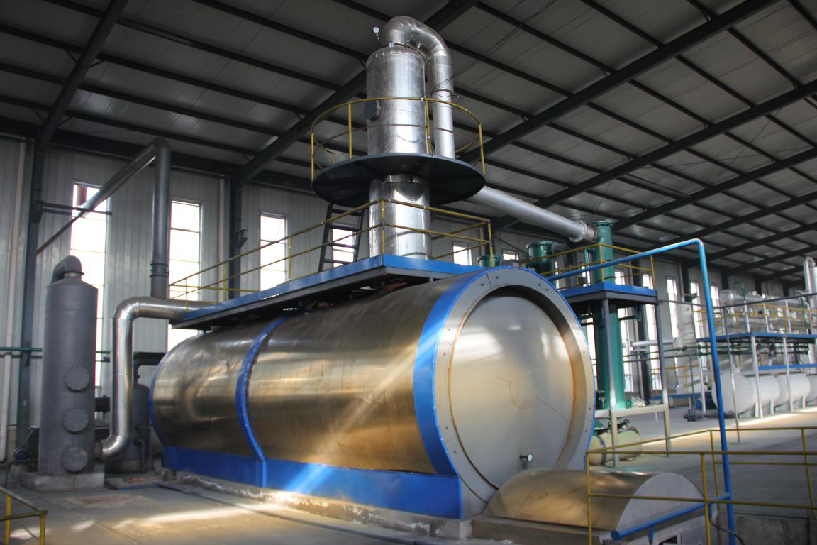
Batch Type Oil Distillation Plant
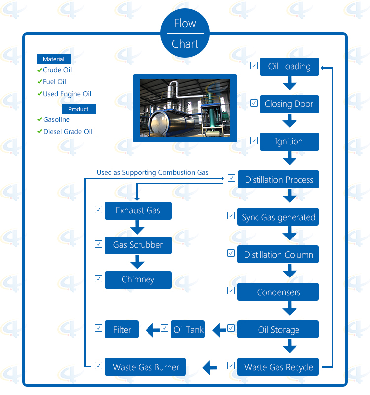
The Waste Engine Oil Distillation Plant is used to refine waste engine oil, crude oil and fuel oil after pyrolysis process into diesel grade oil, gasoline or and base oil. The daily capacity of this plant is about 5-6 tons.

Flow-chat of waste engine oi Distillation Plant

Advantage of waste engine oi distillation plant
1. Unique and original manufacturing and technology with our own formula of our equipments in China;
2. Unique horizontal design, high oil output with about 90% oil yield and 100% conversion rate, highly effective and profitable;
3. Good quality end product oil as the substitution of standard diesel oil in usage;
Automatic submerged welding technology, ultrasonic nondestructive testing, both manual and the automatic safety devices;
4. Sync gas recycling system: fully burned after recycling and utilization, saving fuel and preventing pollution;
5. National patent, unique heat insulation shell: high efficiency temperature keeping, excellent energy-saving effect;
6. High condensing efficiency condensers with more oil output. Good quality oil, longer lifetime, and easy to clean;
7. National patent water film smoke scrubbers: efficient removal of the acid gas and dust of the smoke, environmental friendly to meet related national standards.
Technical Parameter of Waste engine Oil Distillation Plant
|
NO. |
Item |
Technical Parameter |
|
1 |
Suitable Raw Materials |
Waste engine oil, Pyrolysis fuel oil, crude oil |
|
2 |
Structure |
Horizontal Type |
|
3 |
Capacity(24 hours) |
3.5-6.5Mt |
|
4 |
Work Pressure |
Normal Pressure |
|
5 |
Oil Yield |
80%-90% |
|
6 |
Power |
18 kw/H |
|
7 |
Cooling Method |
Cycle water |
|
8 |
Condensers |
4 pieces of Vertical condensers |
|
9 |
Emission Treatment |
New DE-sulfurization Smoke Scrubbers |
|
10 |
Heating Method |
Hot Air |
|
11 |
Type of Installation |
With Foundation |
|
12 |
Noise dB(A) |
≤85 |
|
13 |
Dimension of Reactor(mm) |
Ф2200×6000 Ф2500×8800 |
|
14 |
Operating Mode |
Semi-continuous Operation |
|
15 |
Main Chamber Weight (MT) |
10~13Mt |
|
16 |
Total Weight(MT) |
25~35Mt |
|
17 |
Installation Space Required |
35m*15m |
|
18 |
End Product |
Non-standard diesel oil |
|
19 |
Manpower |
1~2/shift |
|
20 |
Shipment Requirement |
2*40HC=Ф2200×6000 1*40HC+1*40FR=Ф2500×8800 |
Batch Type Oil Distillation Plant
Batch Type Oil Distillation Plant,Batch Distillation Column,Waste Oil To Diesel,Oil Distillation Plant
Shangqiu Jinpeng Industrial Co., Ltd. , https://www.recyclingthewaste.com