After continuous improvement, this technology has matured in the past decade. This technique also uses a water-cooled copper crucible, but the crucible wall is divided into many petals. In this technology, electromagnetic induction generates electromagnetic force while heating the charge, so that the alloy liquid is in suspension or semi-floating state, further reducing the contamination of the charge material by the crucible material. Preparation of rare earth alloys using cold crucible vacuum induction melting furnaces, especially rare earth giant magnetostrictive alloys (which are alloys based on REM2 compounds that produce large strains in magnetic fields, commonly used as Tb0.26-0.32 are very effective The cold crucible vacuum induction melting furnace consists of four parts: electromagnetic induction heating power supply, vacuum melting furnace, vacuum-inert gas system, and electronic control system. The power source can be high frequency or medium frequency, and the frequency is determined based on the weight of the charge. The less the charge, the higher the frequency.The crucible used in this type of smelting furnace is generally made of high thermal conductivity metallic material such as copper, and is divided into some separated petals in the axial direction of the crucible, and each crucible is cooled by circulating water. The heat-resistant insulation material may be filled in between and may not be filled in. Larger smelting furnaces are generally made of metal materials, and small-scale melting furnaces use non-metal (such as quartz) shells. There are two metal melting furnaces. One kind of structure, one is a bottom bet type, the other is a flip pouring type.
The smelting furnace is mainly composed of shells, crucibles, induction coils, power interfaces, die mechanisms, and feeding mechanisms. The temperature sensor and observation window can be set as required. This smelting furnace is also specifically equipped with the injection rod mechanism and inverting mechanism. The injection rod mechanism, invert mechanism and mold mechanism constitute a multi-functional stirring-inverting-casting operating system. In addition, a nozzle for discharging the alloy liquid must be provided at the bottom of the crucible. The plug stem mechanism consists of a plug head, a drive rod, and a power-drive mechanism. The plug head is a component that can be inserted into and block the injection port. The upper end can have short blades and the lower end is connected to the drive rod.
The axis of the drive rod coincides with the axis of the injection hole, which is downwardly coupled by a vacuum-dynamic seal extending from the furnace body and the power-transmission mechanism. The power-transmission mechanism allows the plug head to move up and down and forward and reverse around the axis through the drive rod, and the speed can be adjusted over a wide range. The driving rod is a laminated water-cooled metal sleeve which introduces the circulating water outside the furnace into the inner cavity of the plug head to cool the plug head. The inverting mechanism is located above the crucible and consists of a holding head and a lever. When the alloy ingot is lifted by the plugging rod mechanism, the operating rod can move the holding head near the alloy ingot and manipulate the holding head to invert the alloy ingot. The mechanism can have many structural forms, such as mechanical, electromagnetic, permanent magnet and composite structures. The mold mechanism is below the crucible. It is mainly composed of two parts: the mold tube and the mold holder. The mold tube can be made of metal materials (such as carbon steel, stainless steel, cast iron, copper, etc.), and non-metal heat-resistant materials (such as quartz, alumina, boron nitride, magnesia, zirconia, calcium oxide, nitriding) can also be used. Silicon, rare earth oxides, rare earth sulfides, etc.) The mold tube surrounds the drive rod of the injection rod mechanism, the axis is parallel, the central axis of the distribution cylinder coincides with the drive rod, and the inner diameter matches with the plug rod head. In order to facilitate demoulding, it can be assembled. A gasket with a casting hole made of a high-quality heat-resistant ceramic material may be inserted between the upper opening of the mold tube and the pouring hole, and may be directly connected. In addition, it is generally necessary to provide a heating or heat-retaining device for the mold. Generally, resistance heating and a temperature control device are used.
Glass Bowl Food Choppers
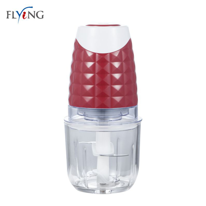
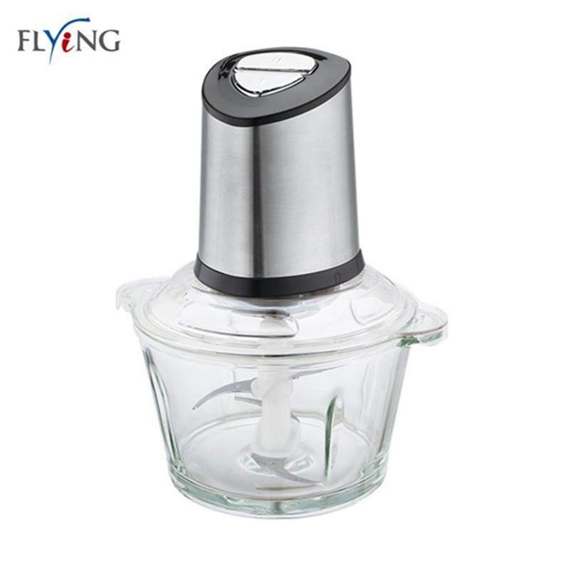
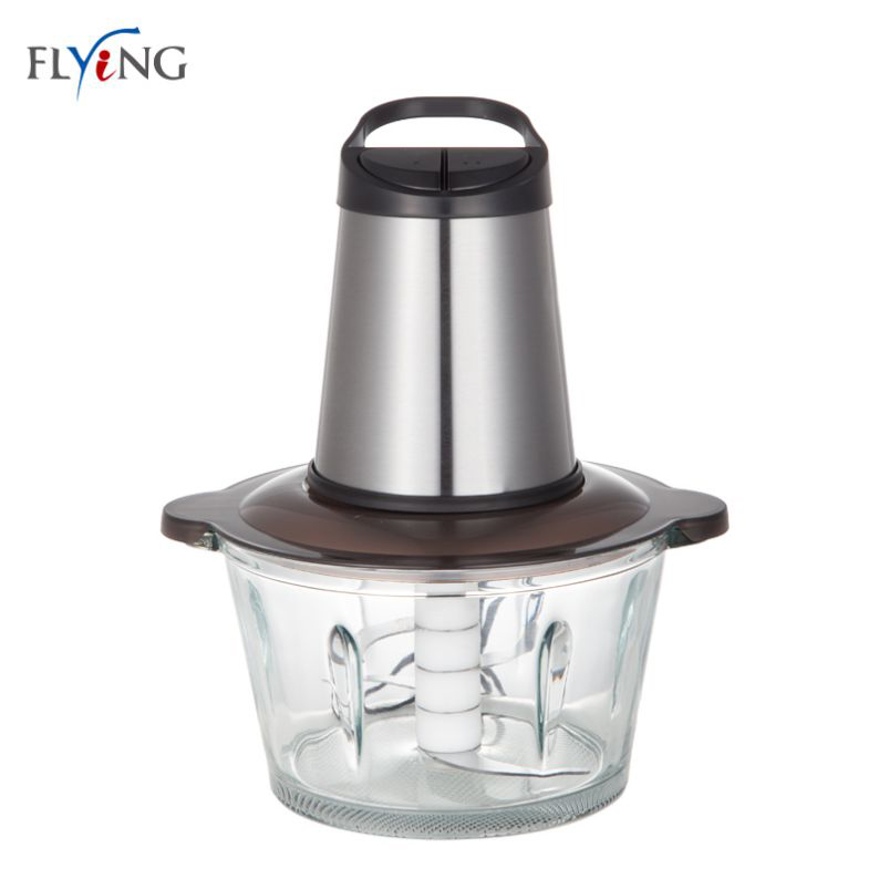
Glass Bowl Food Choppers are our main food choppers. We have 0.6L, 1.2L, 1.8L optional with pure clear and thick glass bowl. Besides, we have molding polyfoam packing for glass bowl and our glass bowl is thick and strong, it is not easy broken. What's more, glass bowl is easy to clean.
Description of Glass Bowl Food Choppers
300W/350W
S/S housing
pure clear and thick glass bowl with double blades
one/two speeds with safety lock
metal gear
6pcs/ctn


Glass Bowl Food Choppers,Glass Bowl Choppers,Kitchen Food Processor,Vegetable Chopper
Flying Electronic Co., Ltd , https://www.electronicjmflying.com