1 ore body occurrence conditions
A lead-zinc ore deposit type is silver lead and zinc sulfide, a total silver lead-zinc circle 8, wherein the largest ore bodies No. â‘¢, accounting for 94% of the whole amount of silver metal total reserves, silver, lead and The zinc industrial ore body is distributed in the fragmentary dolomite marble in the middle part of the second sub-section of the second section of the Middle Cambrian Tianpeng Formation. The north-south strike is 1510m long, the horizontal width is 10~164m, the inclined extension length is 41-359m, and the average extension is 179m. . The minimum thickness of the ore body is 0.97m, the maximum thickness is 19.72m, and the average thickness is 3.47m. The elevation is 819~1333m.
The water system in the mining area is not developed, and there is no surface water body. It is only a seasonal creek and there is no running water. The water filling of the deposit is mainly atmospheric rainfall and rock fissure water. The topography is conducive to the natural excretion of groundwater. The hydrogeological type of the mining area is a simple type with fissure water filling.
The surrounding rocks of the top and bottom of the silver-lead-zinc ore body are schist and marble, belonging to the weak-semi-hard rock group. The schist has low mechanical strength and is a weak rock layer. It is easy to soften when exposed to water and has poor stability. The marble has a slightly higher mechanical strength, is semi-hard and has good stability. The engineering geological conditions of the mining area are medium types dominated by weak-semi-hard rock groups.
2 mining status
A silver-lead-zinc mine is underground mining, which is developed by Pingshuo-slippering and shallow-hole mining. Due to the long history of civil mining in the region, and all of them are disorderly mining, a large number of goafs have been formed above the 1250m elevation, which poses a major safety hazard to the safe production of the mine. The mine has four middle sections of 1095, 1065, 1035 and 1000m, of which 1000m middle section is the main transport flat. At present, the middle section of 1095m has been basically mined, and the middle section of 1065m has been mostly mined. The middle section of the main ore is now the middle section of 1035m. At present, a large number of goafs have been formed within the elevation range of 1135 to 1065 m, which not only causes the surface subsidence of the upper old goaf to affect the surrounding environment, but also poses a certain threat to the current downhole safety production. The ore is associated with higher silver metal and has higher economic value. However, the shallow hole retention method needs to reserve a certain size of the ore column as required, and the ore's ore rock has poor stability, and the pillar It is difficult to recover as planned, which is very easy to cause loss of pillar resources and waste valuable geological resources.
In order to reduce the impact of mining on the surrounding environment, improve the safety of underground operations, and maximize the recovery of valuable geological resources, this paper uses the actual situation of the formation of goaf within the current mining and mining production range of the mine. The tailings of the plant are filled into the underground goaf, and the original single empty field method is changed to the empty field method to recover the post-harvest filling to improve the underground safe production environment, and fundamentally relieve the tailings pressure because the existing tailings pond has been closed. Filter the pressure of the reactor discharge and improve the safety of underground operations, solve the tailings discharge and protect the ecological environment of the mining area.
3 filling system optimization scheme design
According to the current mining situation of the middle section of 1000m and the middle section of 1035m, this paper timely processes the old goaf of the middle section of 1065m and the middle section of 1095m, as well as improving the resource recovery rate as much as possible, and alleviating the discharge pressure of tailings, and using the tailings of the plant to carry out the filling of the underground goaf. Design and optimization.
According to the current situation of the mine and the layout of the filling system, three filling schemes are designed: full tail sand self-flow filling scheme; full tail sand pumping scheme; automobile transportation tailings scheme. In this paper, the above three schemes are compared economically and technically, and the optimal filling system scheme is recommended.
3.1 Full tail sand gravity filling scheme
The filling station of the scheme is located at the 1390m elevation of the old mine part of the Nandangchang lead-zinc mine. The tailings produced by the plant are pumped to the deep cone paste thickener of the filling station, dewatered and concentrated, and then transported by filling and drilling. In the middle section of 1095m, it is transported to each filling working surface through the middle section of 1095m.
(1) Process flow: plant tailings→filling station deep cone paste thickener→mixer→filling middle section→filling work surface.
(2) Engineering and equipment configuration: NGT-9 deep cone paste thickener is used. The inner diameter of the thick pool is 9m, the depth of the dense pool is 10.6m, the dry material handling capacity is 25t/h; the conveying capacity of the screw conveyor is 5~15m3/ h; continuous mixer model is JS3200, stirring capacity is 60m3/h; activated mixer model is GJ503/80, stirring capacity is 60m3/h. The diaphragm pump model is DGMB80/7.5, the filling pipeline length is 2320m, the filling borehole is 260m deep, and the filling tunnel length is 500m.
3.2 full tailings pumping scheme
The program is provided in the South filling station filling pump Slurry transported into the filling station deep cone thickener paste, dehydrated and concentrated by elevation of 900m when the next plant mineral concentration plants pressure filtration plant, plant yield is selected from the tailings using It is transported to the middle section of 1000m and transported to the filling working surface through the middle section of 1000m.
(1) Process flow: plant tailings→filling station deep cone paste thickener→mixer→filling middle section→filling work surface.
(2) Engineering and equipment configuration: NGT-9 deep cone paste thickener is used. The inner diameter of the thick pool is 9m, the depth of the dense pool is 10.6m, the dry material handling capacity is 25t/h; the conveying capacity of the screw conveyor is 5~15m3/ h; continuous mixer model is JS3200, stirring capacity is 60m3/h; activated mixer model is GJ503/80, stirring capacity is 60m3/h. The filling industrial pump model is HSP2180HS, the surface pipeline length is 2030m, and the downhole pipeline length is 2860m.
3.3 Car transportation tailings program
The design filling and mixing station is located at the 1050m elevation of Wukou Road junction, and the middle section of 1000m is used as the main filling middle section. The tailings produced by the plant are dewatered by the plate frame filter press and then transported by car to the tailings yard of the filling station. The loader is fed into the discharge bin, and is transported to the mixer through the electromagnetic vibrating feeder and the large angle belt conveyor. After being evenly mixed, the pump is pumped through the pipeline through the 1000m middle section to the middle section of 1095m, the middle section of 1065m and the middle section of 1035m. The stope is filled with small wells and filled into the goaf.
(1) Process flow: plant tailings→filling station deep cone paste thickener→mixer→filling middle section→filling work surface.
(2) Engineering and equipment configuration: screw conveyor capacity is 5 ~ 15m3 / h; continuous mixer model is JS3200, mixing capacity is 60m3 / h; activated mixer model is GJ503 / 80, mixing capacity is 60m3 / h. The electromagnetic vibration feeder model is GJ503/80, the conveying capacity is 150t/h, the filling industrial pump model is HBMG80, the surface pipeline length is 530m, and the downhole pipeline length is 2860m.
3.4 Comparison and selection of filling system solutions
The technical and economic aspects of the three filling system schemes were analyzed and compared. The comprehensive comparison results of the filling system schemes are shown in Table 1.

According to the above comparison, although the investment cost of the scheme 3 is the lowest, the filling cost is much higher than that of the scheme 1 and the scheme 2, and there is a secondary pulping, which affects the filling effect and the filling quality, so it is preferentially excluded. The investment in Option 1 is slightly lower than that in Option 2, and the filling cost is slightly higher than that in Option 2, but the tailings are hydraulically delivered and the process is mature and reliable. In Scheme 2, the filling slurry is transported far away, and the lift is high, and the filling equipment is long-term. Working under high pressure, there are certain hidden dangers to the normal use of filling equipment. It is understood that there is no similar working condition in China, and the reliability of the equipment cannot be determined. In the first scheme, the tailings conveying process is mature and reliable, and the investment is low. The operating costs are not much different. Therefore, this design is based on the principle of technical feasibility and economic rationality.
4 Conclusion
Whether the selection and arrangement of the mine filling system is reasonable or not has a great impact on the mine filling operation cost. This paper optimizes the design of mine filling system, makes full use of the existing site of the old mine department, and focuses on the comparison of infrastructure investment, operating cost and technical advantages and disadvantages for the three filling schemes. It selects mature technology, low capital investment and operation. The lowest cost option 1, namely the full tail sand gravity filling scheme, provides a certain reference for the design of similar mine filling systems.
references:
[1] Wang Qianyuan, Wang Hailong, Ren Xiaoyun. Mine filling related problems and low-cost filling technology [J]. Mining Research and Development, 2016, 36(01): 42-44.
[2] Xu Jiafu. Optimization Reform Levin new iron ore Filling System [J]. Mining Technology, 2014, 14(6): 22-25.
[3] He Hongtao, Zhou Lei, Xu Wenbin. Optimization and application of temporary cementation filling system in Heshan Iron Mine [J]. Non-ferrous metals (mining parts), 2012, 64 (6): 9-11.
[4] Liu Haijun. Fujia mine filling system problems and solutions [J]. China Mining Engineering, 2014, 43(1): 13-15.
[5] Yan Guangwen. Reconstruction of the full tailings filling system of Laixin Iron Mine [J]. Modern Mining, 2012, 516 (4): 88-89.
[6] Wang Hairui. Reconstruction and optimization of full tailings cemented filling and self-flow conveying pipeline [D]. Changsha: Central South University, 2010.
[7] Yu Runcang. China's filling process innovation achievements and topics that need further research [J]. Mining Technology, 2011, 11 (3): 1-3.
[8] Zhang Changqing. Reconstruction of the north mineralized belt filling system Wushan Copper Mine [J]. Mining Research and Development, 2003, 23 (01): 18-19.
[9] Bi Hongtao, Zhao Guoyan, Dong Junjun. Research on optimization practice of filling system in Xincheng gold mine [J]. Mining Research and Development, 2010, 30(2): 10-12.
[10] Guo Huigao, Mo Yabin, Wang Hu, et al. Research and application of Jinchuan large flow high concentration gravity filling system [J]. Mining Technology, 2015, 15 (03): 25-27.
[11] Zhang Muyi. Optimization of the filling and filling system of Fankou Mine [J]. Mining Technology, 2001, 1(1): 9-11.
[12] Guo Mingming. Design and research of the complete tailings filling system of Taipingshan Iron Mine [J]. Mining Research and Development, 2015, 35(02): 9-12.
Source: Mining Technology: 2016, 16(3);
Copyright:
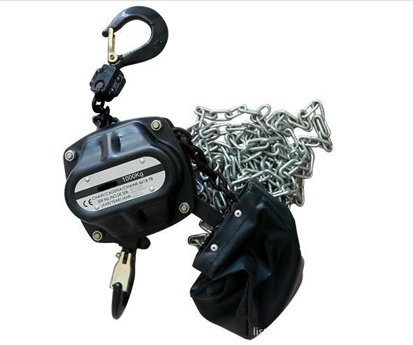
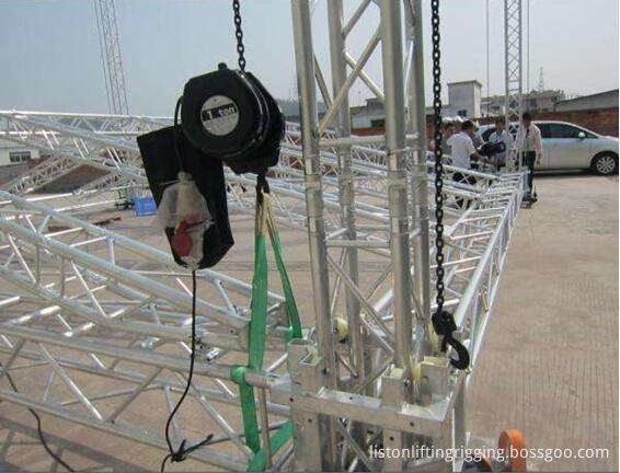
Manual Stage Chain Hoist is specially designed & manufactured for stage inversion or common lifting operation purpose. for example, in stage stereo, lighting, show banner,
campaign activity and steel frame which application is very wide.
1. Clutch: Protects hoist, operator, structure from damaging overloads.
2. With Overload Protection: Designed to prevent lifting of excessive overloads. Helps prevent lifting of dangerous loads.
3. Zinc plated Load Chain to protect against corrosion. Optional black finish available.
4. Low voltage control: 24 and 48 volt optional.
5. Cast aluminum housing, lightweight. Black power coated finish for low visibility.
6. 5-teeth lifting chain wheel
7. Double brake: With mechanical brake
Products ahow


Our Services
1.Client
We treasure and try to understand all the different needs of our clients and seek to forge a long term professional relationship with them. The satisfaction of each and every customer is our main goal and motivation in conducting our business.
2. People
We work as a team and treat each other with respect. Our solid, capable and knowledgeable team is valued as the greatest asset and an integral part of the business.
3. Product
Our products are of HIGH quality standards and always come with certificate of compliance by the manufacturers.
4. Performance
We aim to achieve high level of performance and satisfaction to both our client and people, which include delivering high quality services and treating people with integrity.
5. Free sample and OEM service
We can provide free samples to you and we also have OEM service, we can put your logo on the label and the information you need on the webbing too.

Stage Chain Hoist,Climbing Chain Hoist,Manual Stage Chain Hoist,Electric Stage Chain Hoist
Hebei Liston Lifting Rigging Manufacturing Co., Ltd. , https://www.liftingriggingfactory.com