There are two kinds of involute profiles widely used in practical engineering of involute. (1) Involute Cylinder Involute Cylinder can be seen as a translational motion of the involute along the Z axis along the Z axis. It can be seen that when ; = constant, the involute cylinder equation can be obtained, and Z is the length parameter along the straight bus.
The involute cylinder is an involute straight tooth profile. When Z = constant, the family of involutes of the involute cylinder is described; when λ = constant, the family of straight bus bars describing the involute cylinder is described.
(2) Involute helicoid reference equation (2), when; Z satisfies the relationship Z = Rbtan βb; (3), that is, the involute spiral surface equation r = Rbe (λ θ) - Rbλe1 (λ θ) In the formula of Rbθtanβbk (4), βb is a base circle helix angle.
The involute helicoid can be formed by a spiral motion of the involute on the OXY plane about the Z axis, as shown.
Fig. 2 Involute cylinderFig. 3 Involute helicoid The circular vector function e(λ θ) and e1(λ θ) in equation (4) are developed to obtain the Cartesian coordinate equation of the involute helicoid X= Rb[sin(λ θ) λcos(λ θ)]Y=Rb[cos(λ θ)-λsin(λ θ)]Z=Rbθtanβb(5) It can be seen that the involute helicity is determined only by two parameters. : base circle radius Rb and base circle helix angle βb.
It is worth noting that the spiral AQ in the middle is called the base circular spiral, the cylinder in which it is located is called the base cylinder, the tangent PQ of the base circular spiral is called the straight bus, and the triangle PQT is called the tapered triangle.
It can be seen from equation (5) that when θ = constant, Z = constant, the equation is expressed as an involute, indicating that the end face of the involute helicoid is truncated as an involute; when λ = constant, there is X2 Y2=Rb2(1 λ2)Z=Rbtanβbθ(6) represents a spiral on a cylinder with a radius of Rb1 λ2, and its lead is PS=2πRbtanβb(7). When λ θ=constant, it can be proved that the equation represents an involute A straight line (ie, a straight bus) that is tangent to the base cylindrical helix on the helicoid.
Mapping of the characteristic lines of the involute helicoids. When an ideal involute helical tooth profile is engaged with an ideal standard helical rack, the left and right profiles each form an engaging surface which is tangent to the base cylinder, as shown . The intersection line of the mating surface and the tooth contour surface is a straight bus line, that is, the instantaneous contact line of the rack and the gear meshing; the involute line of the cross section at one end of the tooth profile forms a straight line parallel to the end surface on the mating surface; The cylindrical surface coaxial with the gear is a top cylinder, a root cylinder, a divided cylinder, etc., and the intersection line with the mating surface is a straight line parallel to the gear axis. According to this, various characteristic lines on the involute spiral surface can be mapped to the mating surface.
As shown, NN' is the tangent of the meshing surface and the base cylinder, and is set to the vertical axis (Z axis). The change of the expansion angle λ forms the horizontal axis. Then, the meshing surface of Fig. 4 and the straight busbar are mapped to the plane and the characteristic line 1 and The family of straight lines parallel to the horizontal axis is an involute family, and the condition is: θ=constant, or Z=Rbcotβbθ=constant; 2 the family of straight lines parallel to the vertical axis is a family of helix, and the condition is: λ=constant, or R=Rb1 Λ2=constant; the family of straight lines with the β-angle of the Z-axis is a straight bus family, with the following conditions: λ θ=constant, or Z=-Rbcotβbλ constant; further see that when βb=0, the involute helical profile The face becomes an involute straight tooth profile, at which point the spiral family and the straight bus family are combined into one, becoming a straight bus family parallel to the gear axis.
It can be seen that the points on the mapping plane correspond one-to-one to the points on the contour of the tooth. Moreover, the involute, the spiral and the straight bus are mapped to straight lines on the contour of the tooth, which is convenient for engineering applications.
The relationship between the errors of the involute profile has a series of characteristic curves on the involute profile. Specifically, for the involute straight tooth profile faces, they are an involute family and a straight bus family, and the involute error is specified as the profile error, and the straight bus error is specified as the spiral error. For the involute helical tooth profile, they share the involute family, the straight bus family, the spiral family, and the contact trace family (not covered herein). The involute error is defined as the tooth profile error. It is worth noting that the straight busbar is an important feature line of the involute profile. Although it has not been introduced into the test by national standards, it reflects the instantaneous situation of a pair of involute gear meshes. The error of each straight bus line can comprehensively reflect the actual meshing quality of the gear. As shown, the straight bus error value vector HL at a point of the involute profile is expressed on the mating surface and perpendicular to the straight bus; the tooth profile error value vector Hf is expressed at the intersection of the mating surface and the end section; The line error value vector Hβ is expressed on the intersection of the end section and the indexing cylinder tangent plane. From the analysis shown in the figure, the relationship between the tooth profile, the spiral line and the straight bus line error value is shown as follows: Hf=HLcosβb(8)Hβ=Hfcosα(9) In summary, each tooth profile error value is a straight bus error value. End projection; each spiral error value is the projection of the tooth profile error value on the indexing circle tangent plane.
Further, in the range of the full tooth width, max(HL)-min(HL) is the straight bus error ΔHL, and max(Hβ)-min(Hβ) is the spiral error Δfβ; Max(Hf)-min(Hf) is the tooth profile error Δf.
At the end, the meshing surface is used as the mapping plane, and the involute family, the spiral family and the straight bus family on the involute profile are all characterized by a straight line. It is of great significance to the analysis of the error of the involute gear and the improvement of the accuracy measurement method. Straight bus error analysis and research that directly reflects the meshing quality of the gear has more practical engineering value.
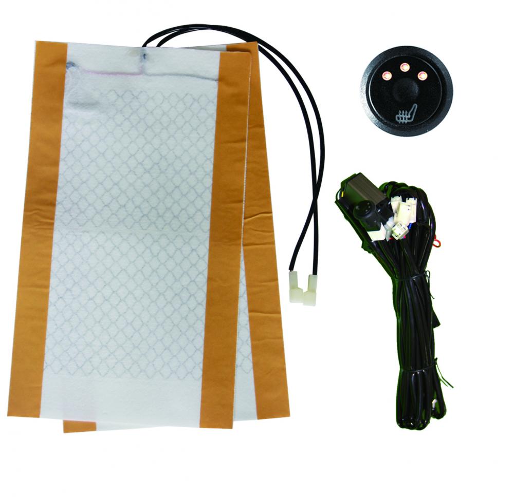
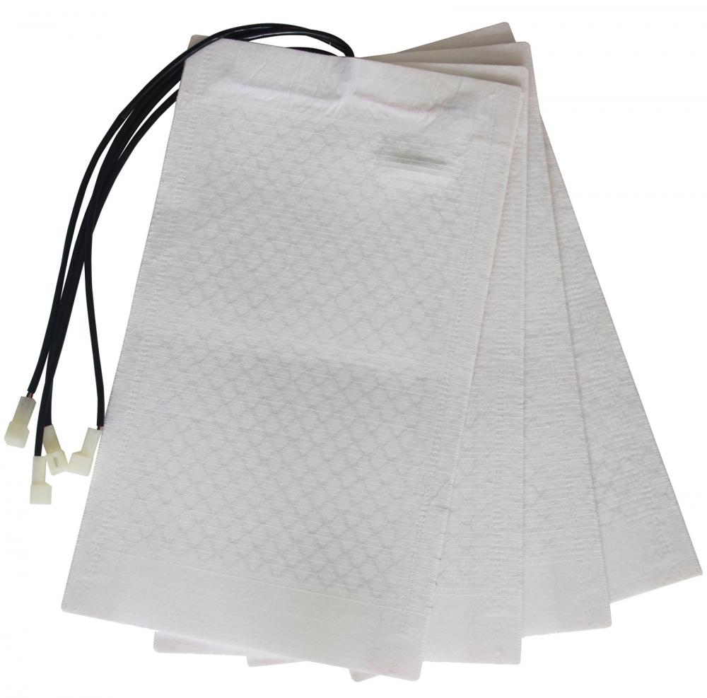
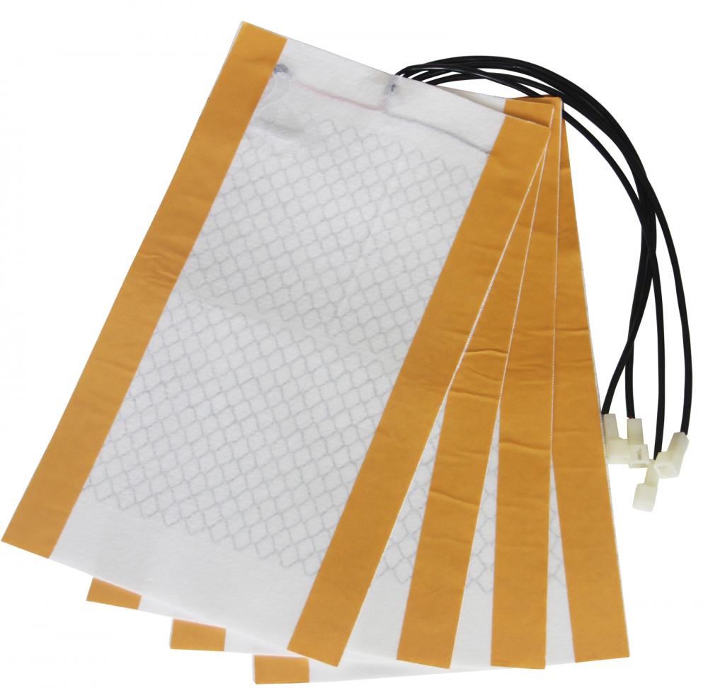
With the ability to heat in just 30 seconds, this is a reliable and efficient heated car seat that you never want to miss. The car seat has the best quality of carbon fiber infrared heating system, which means that it offers super-fast heating to keep the seat warm. Second, to this, the unit allows for constant adjustment of the temperature to suit your needs.


Cars Seat Warmer,Auto Seat Warmer,Cars Heated Seat,Heated Seat Module
JiLin Province Debang Auto Electric Co.,Ltd. , https://www.debangcarseatheating.com